


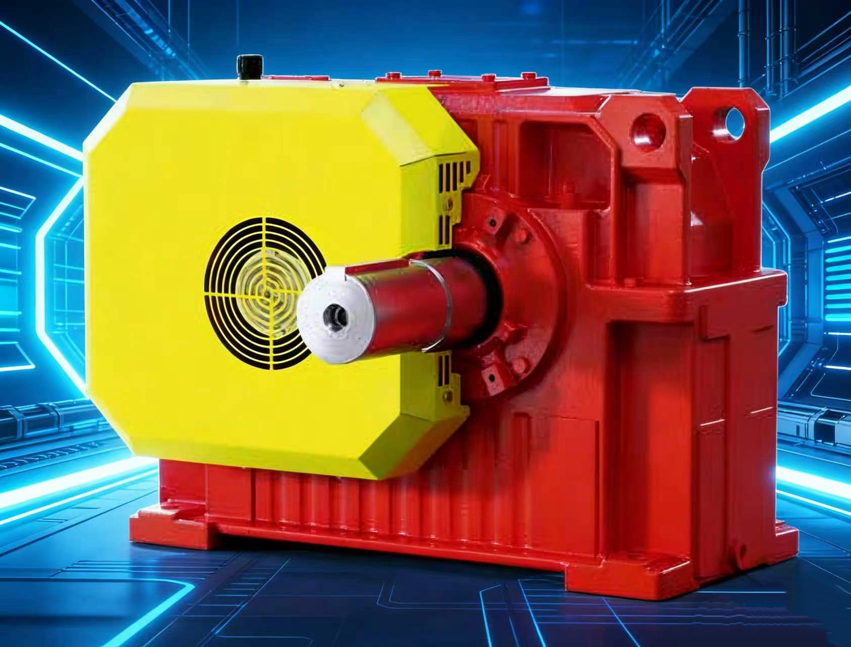
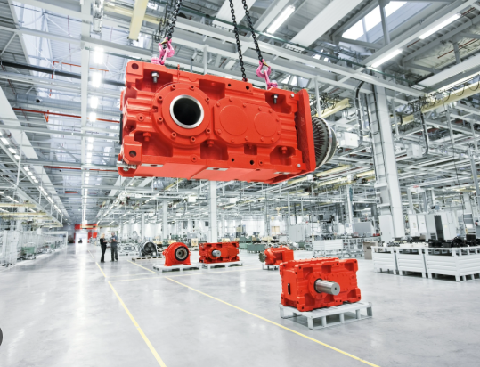
Helical gear reducers sew motor cad MC2PEHF09
${{shopModel.rebate>0?shopModel.discountPriceStr:shopModel.formattedAmount}}
$ {{shopModel.formattedAmount}}
Like
{{item.name}}
Quantity:
Estimated Delivery Date: Apr 03-Apr 03
Frequently Asked Questions
How can I contact customer service?
Do you ship overseas?
How long will it take to get my order?
Specifications
{{item.name}}
{{item.value}}
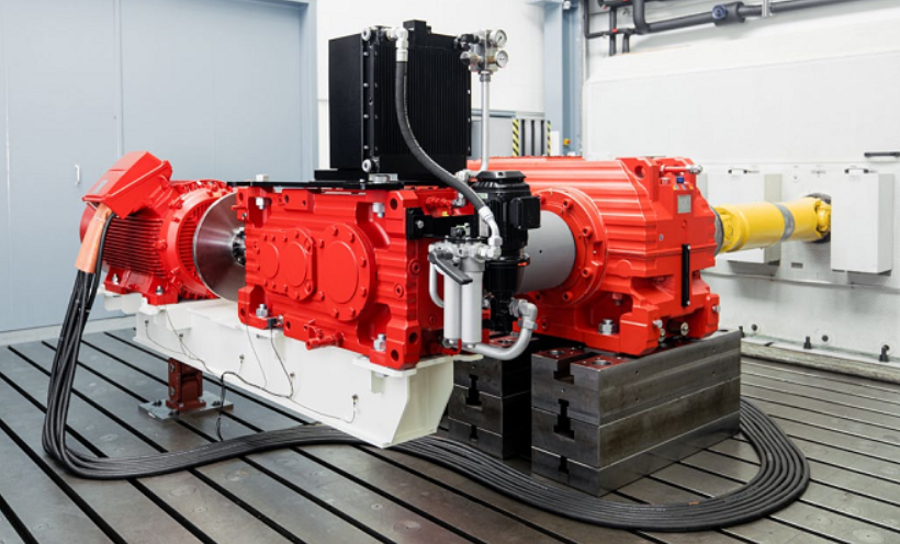
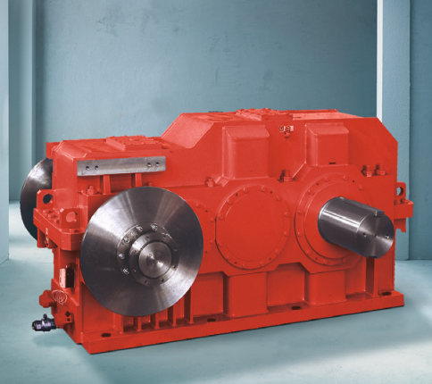
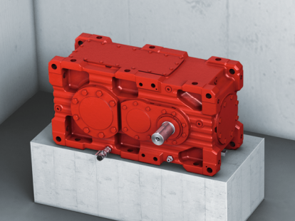
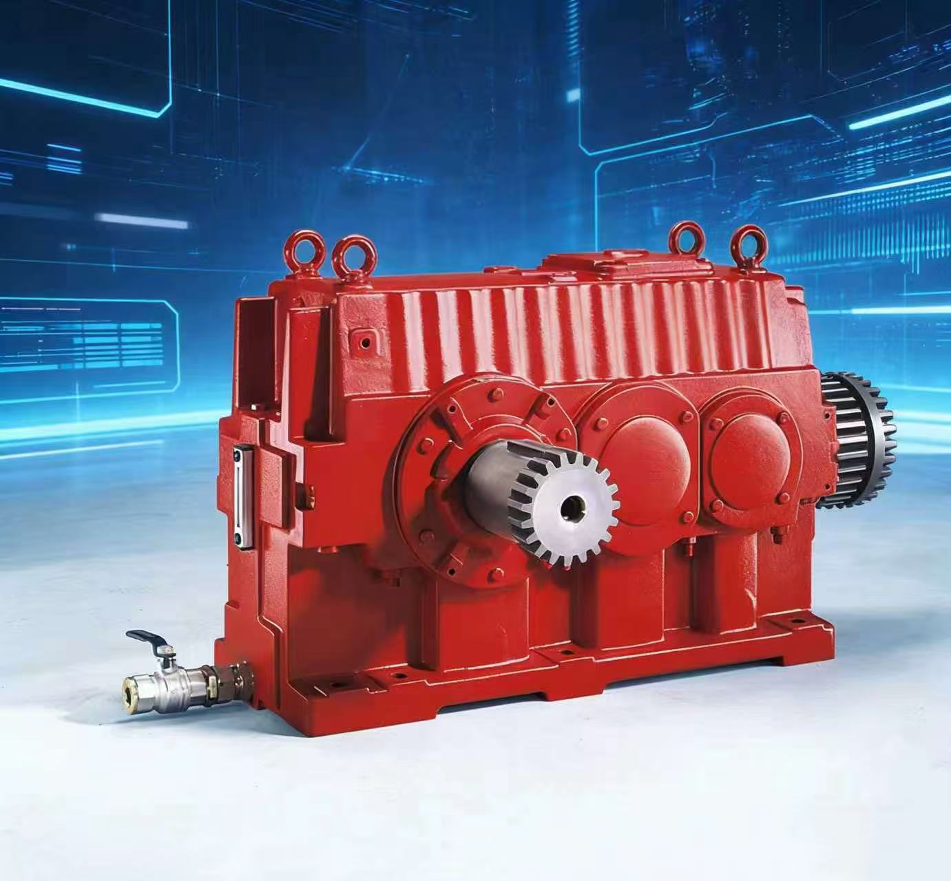
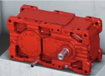
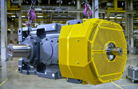
The SEW-EURODRIVE MC2PEHF09 is a high-torque, industrial-grade 2-stage Planetary-Helical gear unit. In the world of "Heavy Drive" engineering, this model represents a hybrid solution: it uses a helical gear stage for initial speed reduction and a planetary output stage to handle massive torque loads.
When searching for CAD data or motor integration for the MC2PEHF09, it is essential to understand the physical envelope and mounting geometry of this Size 09 powerhouse.
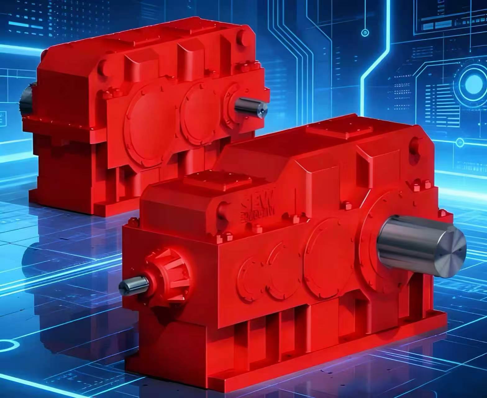
1. Technical Decoding: MC2PEHF09
The model string identifies the specific mechanical "DNA" of the unit:
- MC: Modular Compact Series (Industrial Gear Units).
- 2: Two-stage reduction (1 Helical stage + 1 Planetary stage).
- P: Planetary output. The load is distributed across multiple planet gears, allowing for a much higher torque density than standard helical units.
- E: Extended bearing distance/housing. This version is built to absorb higher radial and axial forces, making it ideal for agitators or heavy-duty conveyors.
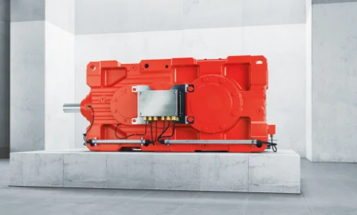
- H: Hollow shaft with shrink disk. Provides a keyless, high-friction connection directly to the machine shaft.
- F: Flange-mounted. The unit features a structural circular flange to bolt directly to the machine frame.
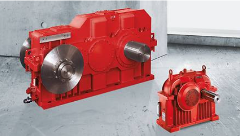
- 09: Size 09. A large-frame unit with a nominal torque capacity typically ranging from 48 kNm to 110 kNm.
2. CAD & Design Integration
For engineers integrating the MC2PEHF09 into a 3D plant layout, SEW-EURODRIVE provides specific tools to generate CAD files (STEP, IGES, SAT, or DWG):
SEW Online Support (DriveConfigurator)
You can generate the exact 3D model by entering the serial number or the specific configuration in the SEW DriveConfigurator.
- Motor Connection: You must specify if the unit is "direct-mounted" to an SEW motor or if it uses an Adapter (AM or AQ) for NEMA/IEC standard motors.
- Mounting Position: Ensure the CAD reflects the correct orientation (M1–M6) as this affects the location of oil plugs and breather valves.
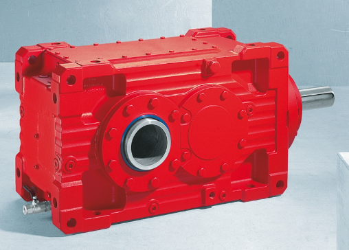
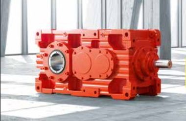
3. Engineering Advantages: The "HF" Configuration
The combination of a Hollow Shaft (H) and Flange (F) is a specific design choice for rigid, space-saving installations:
- Alignment Accuracy: The flange (F) acts as a centering pilot. When bolted to the machine, it ensures the gearbox is perfectly aligned with the driven load, preventing shaft fatigue.
- Keyless Security: The Shrink Disk on the hollow shaft creates a high-pressure interference fit. This eliminates the "play" associated with traditional keyed shafts, which is vital for reversing loads or high-vibration environments.
- Compact Footprint: Because there is no external coupling or coupling guard, the "HF" design significantly reduces the total length of the drive train.
4. Key Performance Specifications (Size 09)
| Feature | Performance Capability |
| Nominal Torque ($M_{N2}$) | ~48,000 Nm to 110,000 Nm |
| Reduction Ratio ($i$) | Typically $i=7.1$ to $i=28$ (for 2-stage units). |
| Efficiency | 97% to 98% (Excellent for heavy-duty power transmission). |
| Housing | Monoblock or split-case high-strength cast iron. |
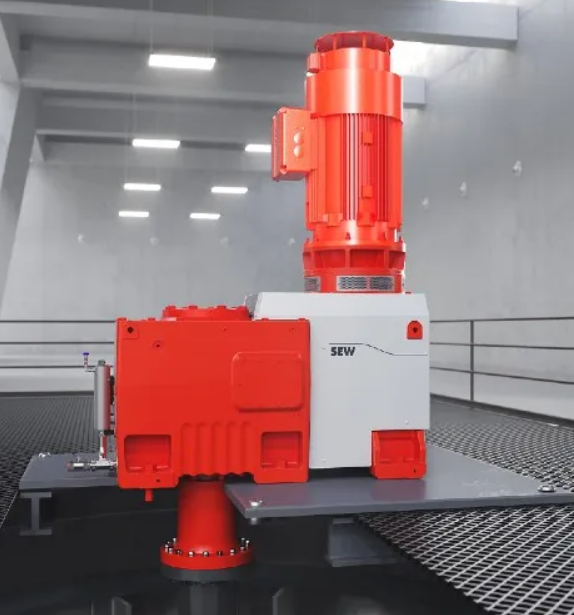
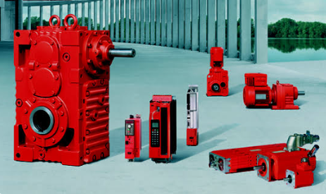
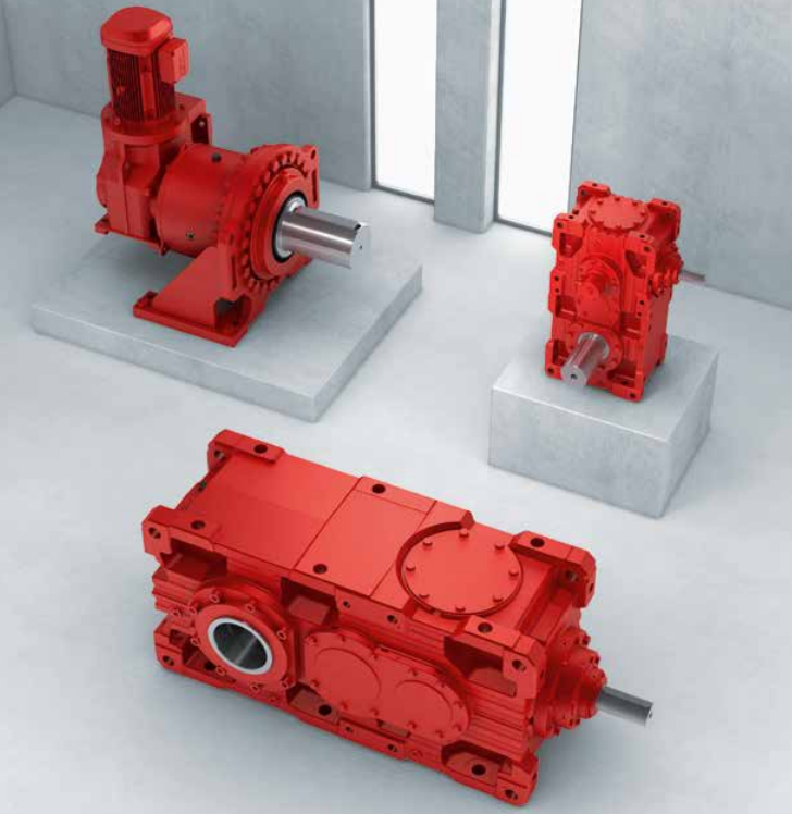
5. Motor Compatibility
The MC2PEHF09 is typically paired with high-power motors. Depending on your CAD requirements, you will see one of two setups:
- Direct Integration: An SEW DRN.. series (AC asynchronous) or DR2.. series motor is bolted directly to the gear unit.
- V-Belt or Coupling Input: If the motor is mounted separately, the CAD will show an Input Shaft Assembly with a pulley or a coupling housing.
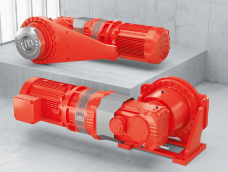
6. Typical Applications
- Large Agitators: The "E" housing supports the mixing shaft's weight while the planetary stage provides the torque to turn thick slurries.
- Screw Presses: High-pressure separation in paper mills or waste treatment.
- Heavy Duty Pumps: High-flow systems requiring 24/7 reliability.
- Conveyor Drives: Specifically head-pulley drives for mining or bulk material handling.
Summary for Designers
When downloading CAD for the MC2PEHF09, always verify the Shrink Disk position (Standard is "Side A") and the Flange diameter, as these are the two most critical interface points for your machine. If you are using a non-SEW motor, ensure the CAD includes the correct Motor Adapter dimensions.
CUSTOMER REVIEWS
{{commentStat.averageRating}}
{{commentStat.total}} Revirews
All({{commentStat.total}})
Images({{commentStat.imgSum}})
5 Star({{commentStat.praiseSum}})


{{item.comments}}